
| Notch filters (= minus filters, narrow band pass filters) reflect a narrow band from a wide specified spectral range and transmit on both short wavelength and long wavelength sides of this band. These filters used in Raman spectroscopy, laser-based fluorescence instrumentation, and multiphoton microscopy.
Typical target reflectance is as high as possible in the high reflectance range and as small as possible in the rest of the specified spectral range. Design approaches: rugate type coatings and conventional multilayer stacks. The advantage of the rugate and quasi-rugate coatings is that they suppress ripples in the transmission spectral ranges. The disadvantages of conventional multilayer solutions is that they might contain layers of four, five, and more materials. Notch filters with narrow and extremely narrow high-reflection zones can be obtained using efficient numerical design algorithms. Two-component solutions typically contain thin layers which may be a problem in the course of the practical realization of the obtained designs. However, it has been demonstrated by several companies that production of multilayer notch filters containing thin layers is realistic. See for example, these references [1], [2], [3], and [4]. |
 |
 |
There are two periodic multilayer structures that can be used as good starting designs for notch filters. Using these structures you may achieve the target width of the high reflection zone and target values of reflectance in this zone. If we denote layer materials as A and B and their refractive indices as \(n_1\) and \(n_s\), then two structures S1 and S2 provide good starting design for notch filters:
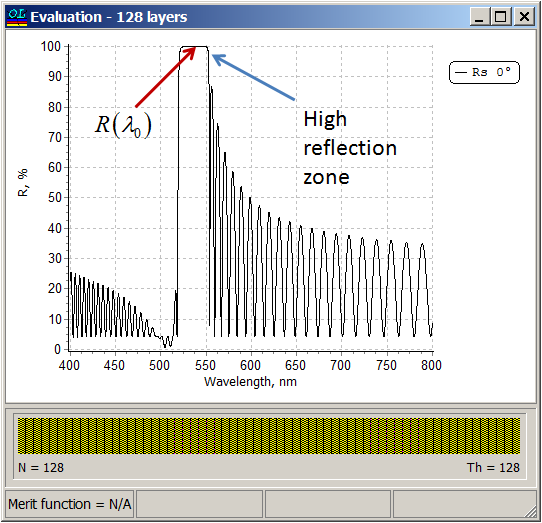
S1: \( n_s | \left((2-p)A\; pB \right)^n |n_a \) S2: \( n_s | \left((4-p)A\; pB \right)^n |n_a \) \(p\) is a fraction quarter wave thickness and \(n\) is the number of layer pairs. Analytical estimations of the reference wavelength reflectance \(R(\lambda_0)\) and the width of the high-reflection zone \(\Delta\lambda_0\) are obtained allow you to find the number of layer pair \(n\) and fraction \(p\) that you need to achieve target specifications.
|
| Reference wavelength reflectance are calculated as follows:
\( R(\lambda_0)=\frac bc, \) (Equation 1) where \( n_a, n_s\) are refractive indices of incident medium and substrate \( b=a_{11}^2 (n_1-n_s)^2+a^2 (n_a n_s\alpha – 1)^2 a_{12}^2\) \( c=a_{11}^2 (n_1+n_s)^2+a^2 (n_a n_s\alpha + 1)^2 a_{12}^2\) \( a=\pi p (n_1=n_2)/2, \; \alpha=-1/(n_1 n_2)\) \(a_{11}=0.5\left[ (1+\sqrt{-\alpha} |a|)^{-n}+(1-\sqrt{-\alpha} |a|)^{-n}\right] \) \(a_{12}=0.5\left[ (1-\sqrt{-\alpha} |a|)^{-n}-(1+\sqrt{-\alpha} |a|)^{-n}\right] /(\sqrt{-\alpha} |a|)\) |
 |
| Example 1:
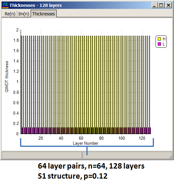
\( n_1=2.35, n_2=1.45, n_s=1.52, n_a=1\), number of layer pairs \(n=64, \lambda_0=532\) nm, \(p=0.12\). R(λ0)=99.9975% |
Example 2:
\( n_1=2.0, n_2=1.5, n_s=1.52, n_a=1\), number of layer pairs \(n=32, \lambda_0=532\) nm, \(p=0.2\). R(λ0)=98.9856% |
| The width of the high reflection zone can be estimated as:
Structure S1: \(\Delta\lambda_0=\displaystyle\frac {4\lambda_0}{\pi} \frac{\sqrt{C^2-1}\;\sin(\pi p/2)}{\left[C+1-(1-p)^2(C-1)\cos(\pi p)\right]}\) (Equation 2) |
ghgh
Structure S2: \(\Delta\lambda_0=\displaystyle\frac {2\lambda_0}{\pi} \frac{\sqrt{C^2-1}\;\sin(\pi p/2)}{\left[C+1-(1-2p)^2(C-1)\cos(\pi p)\right]}\) (Equation 2) |
| where \( C=\displaystyle \frac 12\left(\frac{n_1}{n_2}+\frac{n_2}{n_1}\right)\) | |
| If you have a specified R(lam0) value and width of high reflection zone then using Equation 1 and Equation 2 you can estimate fraction p and number of layer pairs n as follows:
\(\Delta \lambda_0\) –> p from Equation 2 –> n from Equation 1 See the details on the next page. |
Here you can NOTCH CALCULATOR presented above. Simply press Calculate button. |
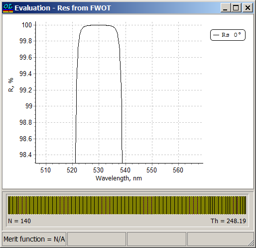
| Example: \(n_1=2.35, n_2=1.45, n_a=1.52, n_a=1\), width of high reflection zone \(\Delta\lambda_0=16\) nm, reflectance in the vicinity of the central wavelength 532 nm is R(λ0)=99.99%.
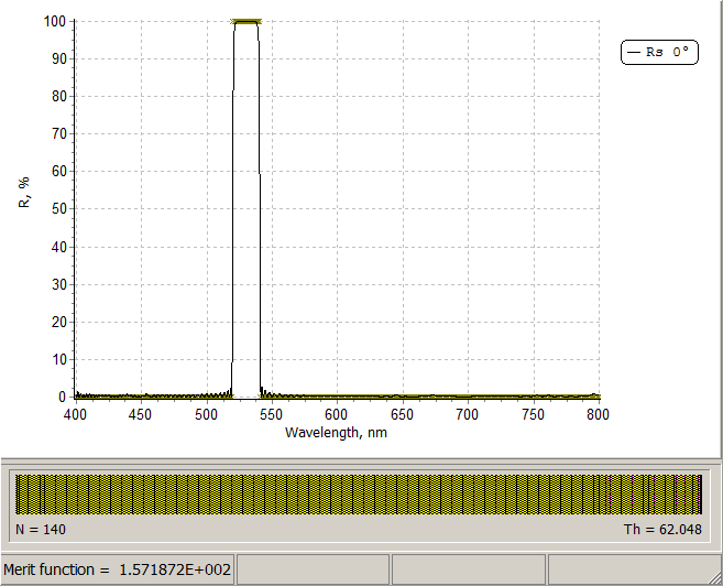
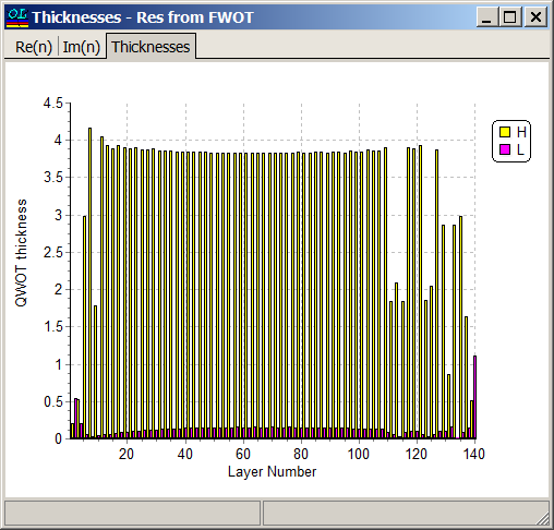
Using NOTCH CALCULATOR (Columns F,G or I,J) we find that in the case of structure S1 \(p=0.06\) is suitable and in the case of structure S2 \(p=0.12\) is suitable. Specifying \(p=0.12\) (Cell B6), we find from Columns A and D that starting from \(n=56\), R(λ0)>99.99%. Specifying a starting design with \(n=64\) (128 layers) and p=0.12, i.e. \(n_s |\left(3.88 A \;\;0.12 B\right)^n| n_a\) and applying need optimization technique, we obtain a 140-layer design shown in the right pane.
|
 |
|
Layer thicknesses of the starting design are 220 nm and 11 nm.
Thicknesses of almost all layers in the final design are 217 and 12 nm, that is very close to the layer thicknesses of the starting design. Width of the high reflection zone is 16 nm and reflectance in the high reflection zone takes the values > 99.99%.
See the details in the publication: T.V. Amotchkina, “Analytical estimations for the reference wavelength reflectance and width of high reflection zone of two-material periodic multilayers,” Appl. Opt. 52, 4590-4595 (2013).
|
| OptiLayer allows you to specify a stack having period with varying optical thicknesses:
\[ \left(\left(a\cdot iL+b\right)H\left(c\cdot iL+d\right)L\right)^n\] where \(a, b, c, d\) are continuous variables , \(iL\) is layer number in the design. More complicated example. You can achieve a narrow bandwidth of a standard quarter wave stack by shifting the ratio of high and low index values of a half wave pair in the stack: \[\left( aH \; \left(2-a\right)L\right)^{(N-1)/2} aH \] where \(a\) is the fractional quarter wave thickness and \(N\) is the total number of layers. With \(a=1\) we obtain a standard quarter wave stack. In order to suppress ripples in the low reflectance zone, we can apply apodization to the parameter \(a\): \[ \left( T_H(i) H\;\; T_L(i)L\right)^n\] \[ T_H(i)=a \exp \left[-\left(i-N/2\right)^2/(2C^2)\right], T_L(i)=2-T_H(i) \] where \(C\) is expressed from FWHM of the Gaussian function by: \[ C=FWHM/\left[2\sqrt{2\ln 2}\right] \]
|
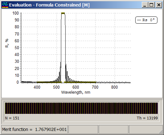
Example: Reference wavelength \(\lambda_0=532\) nm, spectral range of interest is from 400 nm to 700 nm, high reflectance zone is \(\lambda_0\pm 8\) nm.
Layer refractive indices are 2.14 and 1.49, refractive index of the substrate and incidence medium are equal to 1.52 (immersed case) Reflectance of one of the solutions obtained with the help of formula constrained optimization: |
 |
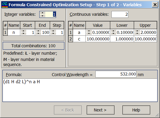
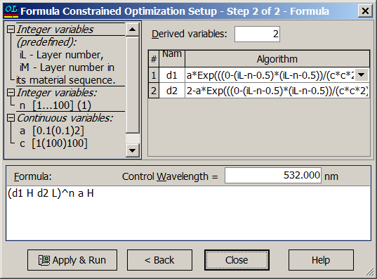
| In OptiLayer this structure can be specified and optimized with respect to three parameters: \(a, \;C\) and \(n=N/2\). The structure can be specified in the two step dialog: | Parameter \(a\) can be varied in the range from 0.1 to 2, parameters \(C\) is from 1 to 100, number of layer pairs \(n\) is from 1 to 100. |
 |
 |